
CSiBridge: An Integrated Bridge Design Technology
CSiBridge has been developed as the ultimate, easy-to-use, integrated software program for modelling, analysis, and design of bridge structures. The ease with which all of these critical tasks can be accomplished makes CSiBridge the most versatile and productive bridge design package in the industry. Welcome to the new world of CSiBridge!
A bridge can be analysed in CSiBridge by generating a model, to determine the response of bridge structures to the weight of vehicle live loads which it will carry to fulfil its objective. Considerable power and flexibility are provided for determining the maximum and minimum displacements, forces, and stresses from multiple lane loads on complex structures, such as highway interchanges. The effects of vehicle live loads can be combined with static and dynamic loads, and envelopes of the response can be computed.
The bridge model to be analysed can be created using easy to use templates accessed through the File > New command or a general F.E.M. model can be built manually using frame, shell, solid and link elements. Alternatively, a mixed approach can be used wherein part of bridge model can be generated using templates and remaining model can be completed manually by adding frame or finite element objects. The superstructure can be represented by a simple “spine” (or “spline”) model using frame elements or it can be modelled in full 3D detail using shell or solid elements. A spine model is the simplest model as it gives the complete response of a bridge structure quickly to get a “feel” of the problem at hand.
Lanes are defined that represent a zone on the bridge where the live loads can move on the superstructure. Lanes may have width and can follow any straight or curved path. Multiple lanes need not be parallel or of the same length so that complex traffic patterns may be considered. The program automatically determines how the lanes load the superstructure, even if they are eccentric to a spine model. Conventional influence lines and surfaces for loading of each lane can be displayed for any response quantity. Vehicle live loads can be selected from a set of standard highways and railway vehicles or users can specify their own vehicle live loads. Vehicles are grouped in vehicle classes, such that the most severe loading of each class governs. Wheel loads for a vehicle needn’t be at a constant distance and may be at a variable distance and CSiBridge will automatically workout the maximum response for a variable axle load too!

A Segmental Bridge Model
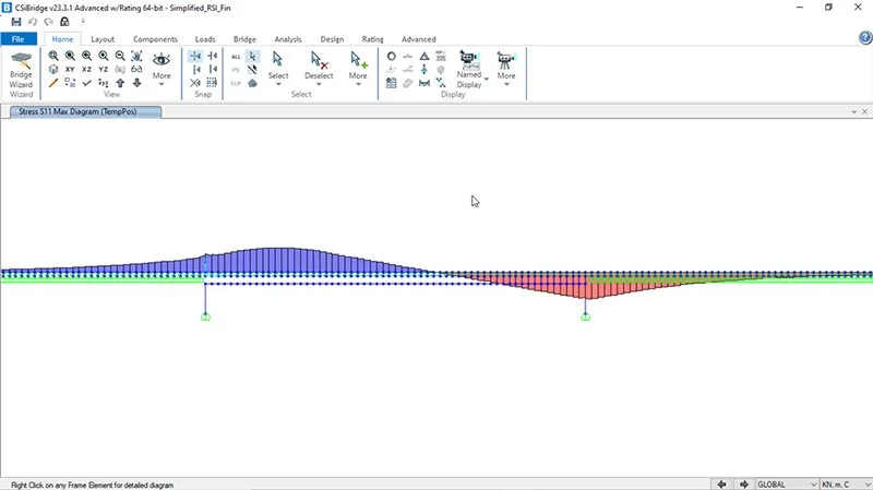
RSI Analysis Rail Stresses
History And Advantages Of CSiBridge
Bridges are a very special class of structures. They are characterized by their complexity in bridge geometry and loading. The geometry of a bridge structure is defined by a number of features that include the alignment (both vertical and horizontal) and the superstructure type. The geometry of a bridge may become more complex when certain features of the bridge vary across spans such as girder depths, deck widths and girder properties. Support conditions can also contribute to the complexity of a bridge model.
Recognition of the unique characteristics of the bridge structure led to the development of CSiBridge more than ten years ago. Originally a bridge module was added to SAP2000, which gave users the ability to generate simple and complex bridge models using all of the powerful features within SAP2000. Now, the analysis, design and rating of simple to complex bridges may be handled using a single program: CSiBridge.
The all new CSiBridge incorporates a ribbon-based interface that provides for an easy-to-use and intuitive workflow. CSiBridge’s parametrically defined bridge models greatly reduce the modelling effort on the part of the user. Deck-to-girder and superstructure–to-substructure connectivity is all handles internally by CSiBridge. Specification of support bearings and foundation modelling are all easily definable. Although the current CSiBridge looks radically different from its predecessors (SAP2000/Bridge).
its mission remains the same: to provide the profession with the most efficient and comprehensive software for the analysis, design and rating of bridge structures. CSiBridge also serves up the latest developments in numerical techniques, solution algorithms and design codes, including automatic finite element meshing of complex object configurations, very accurate shell elements, sophisticated post-tensioning loads and the most recent IRC steel and concrete design codes.
What CSiBridge Can Do?
CSiBridge offers the widest assortment of analysis and design tools available for the engineer working on bridges. The following list represents just a portion of the features included in the CSiBridge software:
- Bridge Analysis Options
- Staged Construction
- Cable-Stayed Bridge
- Stress Ribbon and Extradosed bridges
- CSiLoadOptimizer to find cable loads to have a desired Bridge profile
- Influence Surfaces
- Superstructure Design
– Steel and Concrete
- Load Rating
- Results and Output
- Bridge Animations
- Automated step-by-step Seismic Design of Bridge including Nonlinear Pushover and/or Time History Analysis
And much, much more!
- Bridge Wizard
- Bridge Object Modelling
- Section Designer
- Parametric Deck Sections
- Lanes and Vehicles
- Rail Track modelling for completely automated Non-Linear Rail Structure Interaction analysis
- Bearing and Bridge Pier Modelling
- Post-Tensioned Box Girders
- Pretensioned Precast Bridge sections
- Cast in place (CIP) or precast Segmental Bridges
- Foundation Modelling including complex soil modelling
- Loading and Analysis
An Integrated Approach
CSiBridge provides a powerful way to create and manage simple or complex bridge models. The bridge is represented parametrically with a set of high-level objects: layout (alignment) lines, bridge bearings, bents (pier supports), abutments (end supports), deck cross sections, variations of bridge section along the longitudinal and transverse direction, prestress tendons, bridge lanes and rail track definition and so on. These objects are combined into a super object called a Bridge Object. Typically, a single Bridge Object represents the entire structure, although you may need multiple Bridge Objects if you have parallel structures or want to consider merges or splits or want to analyse a double or triple deck bridge.
The Bridge Wizard is available within CSiBridge to guide you through the process of creating a bridge model and help is available within the wizard itself. An important thing to understand is that the parametric model of the bridge exists independently from the discretization of the model into elements. Options are available to discretize the Bridge Object as frames (spine model), shells or solids and to choose the size of the elements to be used. Discretization can be changed at any time without affecting the parameterized bridge model. When the discretization is changed, the previously generated elements are automatically deleted and new elements created.
An advanced tab of commands is available to add elements to the model to represent features of the bridge that may not be provided through the primary workflow tabs (e.g., Layout, Components, Loads, and so on). These elements will not be affected by changes to the Bridge Object or its discretization, although it may be necessary to move or modify them if the geometry of the bridge is changed.
Modelling Features
Two types of live-load analysis can be considered:
1. Influence-Based Enveloping Analysis - Vehicles move in both directions along each lane of the bridge. Using the influence surface, vehicles are automatically located at such positions along the length and width of the lanes to produce the maximum and minimum response quantities throughout the structure. Each vehicle may be allowed to act on every lane or be restricted to certain lanes. The program can automatically find the maximum and minimum response quantities throughout the structure for placement of different vehicles in different lanes. For each maximum or minimum extreme response quantity, the corresponding values for the other components of response can also be computed.
2. Step-By-Step Analysis - Any number of vehicles can be run simultaneously on the lanes, each with its own starting time, position, direction and speed. Step-by-step static or time-history analysis can be performed, with nonlinear effects included if desired. For most design purposes the envelope-type analysis using moving-load load cases is the most appropriate. For special studies and unusual permit vehicles, the step-by-step approach can be valuable as it also provided full correspondence. The basic steps required for these two types of analysis are as follows.
3. For Both Types of Analysis - Create a structural model using the Bridge Wizard or the work-flow oriented tabs (e.g., Layout, Components, Loads and so on).
- Define lanes that specify the location on the bridge where vehicles can move
- Define vehicles that represent the live load acting in the lanes
4. For Influence-based Analysis -
- Define vehicle classes that group together one or more vehicles that should be enveloped.
- Define moving-load load cases that specify which vehicle classes should be moved on which lanes to produce the enveloped response.
- Specify bridge response parameters that determine for which elements moving-load response should be calculated and set other parameters that control the influence-based analysis.
- After running the analysis, influence lines can be viewed for any element response quantity in the structure, along with envelopes of the responses for those elements requested in the bridge response.
5. For Step-by-Step Analysis -
- Define load patterns of type ‘Bridge Live’ that specify which vehicles move on which lanes, at what speed and from what starting positions.
- Apply the bridge-live load patterns in multi-step static load cases or in time-history load cases if dynamical effects are of interest.
- After running the analysis, options are available to view step-by step response or envelopes of response for any element in the structure. A video can be generated showing the step-by-step static or dynamic results.
Both types of bridge analysis may exist in the same model. Additional load patterns and load cases can be created and the results of those can be combined with the results for either type of bridge analysis.
Analyse The Bridge For Rail Structure Interaction
Modern railways have rail expansion joints far apart and the rails are continuous over bridge deck expansion joints. In such cases it is essential for the bridge designer to make a study of rail structure phenomenon. The stiffness of railway track is nonlinear, and the stiffness of loaded and unloaded track is different. The bridge and railway track affect each other and to study the effect of their interaction the railway track must be modelled as nonlinear support and the nonlinear analysis should be done to find rail stresses.
In CSiBridge modelling of nonlinear track stiffness, the layout of railway track is automated. So, an engineer can model the rail structure interaction effects in the bridge model very conveniently.
Analysis Features
Static and dynamic analyses, including the effects of post-tensioning and temperature, can be carried out for any number of user-defined load cases, and the load cases may be combined into any number of load combinations. Hyperstatic analysis is also available and is based on a predefined static load case.
Users have the option of modelling the superstructure as spine, shell or solid object models. For curved steel girder bridges it is recommended that the steel girders be modelled as shell elements so that warping stresses can be captured.
Nonlinear and time history analyses are also available. The response of a bridge structure supported on bearings and foundation springs having linear and/or nonlinear properties may be handled by CSiBridge. Time history loadings may be defined as transient or periodic functions and may be defined as an acceleration or load pattern type. Time history loading using multiple support excitations may also be performed. Additionally, nonlinear staged construction analyses may be conducted to mimic the effects from construction sequencing and evaluate duration or time effects on the material behaviour. The analysis output may be viewed graphically or displayed using a special force/stress/design output form. The output results may be displayed in tabular output, sent to a printer and exported to a database or spreadsheet file.
CSiBridge also provides dynamic analysis capabilities through modal frequency or time history analysis. These capabilities allow for investigation of things such as deck vibrations from vehicle live load effects.
Design Features
CSiBridge uses the SAPFire analysis engine, the state-of-the-art equation solver that powers all of CSI’s software. This proprietary solver exploits the latest in numerical technology to provide incredibly rapid solution times and virtually limitless model capacity.
Superstructure designs can be performed on a variety of superstructure types, including steel girder and prestressed concrete precast I-girder, bulb tees, box and multicell box girders. The steel girder design allows engineers to optimize the design such that the girder properties may be resized and checked interactively. Stress, flexural, and shear designs in accordance with the IRC, AASHTO LRFD 2012 (steel and concrete), AASHTO STD 2002 (concrete), CAN/CSA-S6-06, and EUROCODE. The steel design results include a number of design plots that allow the user to view demand and capacities for shear and flexure design results.
New international vehicles have been added so the user may establish the member demands. Future releases of CSiBridge will include other international code checks.
Seismic Design Features
A powerful automated seismic design feature is available to engineers using CSiBridge. The automated seismic design feature automatically accounts for the column cracked section properties, column plastic hinges, pushover load case definitions and demand verses capacity evaluations. The user only needs to define the bridge model, the response spectrum and seismic design parameters. The analysis and design process can then be fully automated.
Bridge Rating Features
The AASHTO 2011 LRFD load rating of bridges has been implemented within CSiBridge. The load rating of a bridge may be performed for any predefined or user defined vehicle, including overload vehicles.
Conclusion
With automated modelling, design and seismic design options CSiBridge is one of the best software on the market today. This is advantageous for engineers involved in metro bridge projects as segmental bridges and RSI analysis both have been automated in CSiBridge. Interestingly there are no separate modules to buy and maintain and only one product offers a user all options for a comprehensive analysis and design of Bridge Structures!

For further information,
visit: www.csiamerica.com