
Pre Engineered Building Structures - Discussions on Latest Trends

Er. Dr. Amit Melani
Consulting Structure Engineer and Director
Amit Melani & Associates
Indore

Dr. Rakesh Khare
Professor
Civil Engineering & Applied Mechanics Department
Shri G.S. Institute of Technology & Science
Indore

Er. Akshay Jain
Manager
(Civil Design)
Altis Industries Pvt. Ltd. Indore
In India, recently the use of Pre-Engineered Building (PEB) structures of steel is increased due to constant demand of single storey clear span buildings for warehouses, factories etc. and also being efficient in terms of economy, aesthetics and safety. Pre Engineered steel buildings are fabricated fully in the factory after complete designing, then it gets transported to the site in a complete knockdown condition and all the components are assembled and erected at the site. Generally, tapered sections made with thin plates are used to achieve the desired configuration of various members of building which is a combination of hot-rolled sections, cold-formed members and built-up sections. From typical trussed roof building, the clear internal appearance of PEB steel structures are much more appealing and require less maintenance and heating.
In the horde of competition, current design practices of PEB steel structures adopted by many PEB suppliers and/or vendors are lacking in order to follow some basic codal provisions. Also, in their continual efforts to achieve economy it is observed that PEB suppliers neither follows one country code at a time for a structure nor they use all clauses of atest version of one code, thereby resulting in serious damages to structure by different member failures, loss of money and sometimes lives.
Design Approach by PEB Suppliers
The analysis of any structure is always universal, though design need to be done following the code of a country (or suitable nearby country code, if country does not have code) where structure is going to be built. However, it is observed some PEB suppliers adopting mixed code philosophy giving emphasis to achieve economy and sacrificing structure safety due to lack of knowledge and structural behavior phenomenon.

Fig.1: Components of PEB Steel Shed
This can be understood with an example - if a PEB structure is going to be built in India, the load calculations need to be carried out as per the latest revisions of IS 875. Thereafter, the structural member design need to be done using latest revisions of IS 800 for main frame members and IS 801 for thin rolled secondary members (purlins and girts etc.). But, to make superstructure most economical and in order to give competitive quotations, most of the PEB vendors select codes as per their choice i.e. for a structure to be built in India they might calculate the loads as per IS 875, but do the structural design of members as per American codes like AISC-10 or ASCE-07 using Load and Resistance Factor Design (LRFD) or preferably Allowable Stress Design (ASD) methods where load combinations like (DL+0.6WL) favor the structural design to achieve lowest weights of members. Furthermore, it is observed in the studies that revision in ASCE-7 (05) to ASCE-7 (10) is the increased wind speed about 30% associated with risk category, which is then counter balanced by revising load combinations from 1.0 to 0.6 in ASD load combination and from 1.6 to 1.0 in LRFD load combination. The PEB suppliers using these combinations with Indian basic wind speeds thereby reducing wind loads by 40% creating anomaly in structural design either due to lack of understanding of design philosophy or they are over smart hiding facts with client.
Some PEB vendors select some clauses of previous versions and other clauses of latest version of the code for designing different parts of same building. This style is not the same every time, PEB designers are on constant research and trials by using codal provisions of various countries with different clauses to minimize total weight of the structure to be supplied. This varied design philosophy is not acceptable and is legally invalid. Beside this, if the loads and codes are not specified by the client/buyer, it is binding on the PEB supplier to use the local/ regional codes of practice for structural design. There are various factors on which the evolution of code of practices is based like weather/climatic conditions, material properties, resources available, manufacturing skills, transportation, assemblage, erection, finishes, maintenance etc. Hence, it is unacceptable to use all the provisions and resources as per Indian origin but designing the structure using American codes.
Unfortunately, mostly the structural engineers in India are RC design based and are not conversant with various aspects of steel design like pointed out above. Also, it has been seen that when such designs are submitted by PEB vendors for approval are gladly accepted without any comments. The above discussion stated here is also due to the misconceptions of most of the clients, few architects and engineers in India who feels that American codes are better than Indian codes. We are very fortunate enough to have all codes available for the design of all the parts of a PEB structure regardless of adopting jumping code procedure.
Deficiencies and Remedial Measures Observed at Sites due to Mixed Code Phenomenon used by PEB Suppliers
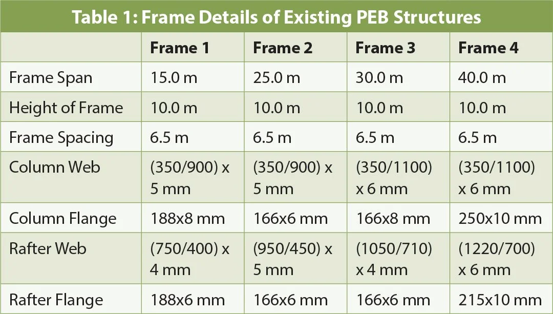
Based on site visits and structural drawings available, data collection of some existing PEB structures supplied by PEB suppliers is done and observations are made based on design calculations and visual inspection. The frames are redesigned as per IS800:1984 and IS800:2007 and observations are made, thereafter based on observations remedial measures to fulfil code requirements are suggested and differences in design and weights after remedial measures are calibrated.
The frame details are tabulated here ->
Observation No. 1: It is observed that flange and web thicknesses are below code based minimum thickness limits resulting in warping of column and rafter web plates during erection under self-weight (Fig. 2).
Observation No. 2: As shown in Fig. 3 below, it is observed that MS rods or single pipe or single angle is used as bracing member with higher slenderness ratios for tensile forces. It is found that the slenderness ratio of such members is beyond code based limit of 350.
Observation No. 3: As per clause 3.8 (IS800:1984) of the code, the minimum thickness criteria for the members are not followed.
Observation No. 4: Invariable deflection in girts and purlins is observed at sites, reason may be section is under designed and deflection limits are not followed as per code based limits (Fig. 4).
Observation No. 5: As per clause 6.7.3 (IS800:1984) in plate girders (Rafters) minimum stiffeners shall be provided but members are provided without any stiffeners.
Observation No. 6: As per IS 875 part 2, Table 2, except for maintenance, the live load should be 0.75kN/m2 for not accessible roofs. But lower values of live load are considered in design

Fig. 2: Columns & Rafters with Buckled Webs


Fig. 3
Tension Rods used Exceeding Slenderness Ratio Limits

Fig. 4: Deflection in Top Girt
The existing frames designed and constructed at sites are found deficient (Table 2) with respect to codal recommendations, therefore remedial measures for those frames are suggested to make them structurally safe. Apart from this, differences in their weights before and after remedial measures are compared.
Remedy No. 1: As the plate size shall be 2.0 mm greater than the weld size, therefore extra 4.0 mm thick plates need to be welded on flanges so that the web depth to thickness ratio and flange width to thickness ratio limit for the section becomes as per code requirements.
Remedy No. 2: Bracing member required as per design is NB-80 or equivalent. However, at few sites MS rods are used as bracings for which slenderness ratio is not satisfying the required limits as per code. Therefore, MS rod bracings should be replaced by any member satisfying slenderness limits as per the code.

Remedy No. 3: As per code, the minimum thickness for steel exposed to weather is 8.0 mm and for steel not exposed to weather is 6.0 mm. Frame 1, Frame 2 and Frame 3 has thicknesses of 5 mm or 4 mm in column webs and/or rafter webs which is less than required. However, Frame 4 fits well for this clause. To rectify this, extra plate shall be welded to satisfy code requirements.
Remedy No. 4: The exceeding deflection can be corrected by replacing members or additional supports in between to share loads or local member strengthening shall be done.
Remedy No. 5: Clause 6.7.3 checks the requirement of stiffeners in webs; here it is found that all frames lacks to satisfy this clause having lesser web depth to thickness ratios. For Frame 1 and Frame 2, 8-10 mm thicknesses are required and for Frame 3 and Frame 4, 10-12 mm thicknesses are required in column and/or rafter webs. Extra plates (4.0 mm thick minimum) need to be welded on webs for its full depth to make them stiffened webs. Alternatively, stiffeners need to be provided as per provisions mentioned in IS800:1984.


Remedy No. 6: In order to make lighter structures, lower live loads are used which are not acceptable. Therefore, sections should be revised or some extra plates should be welded so that the structure is stable if checked for code based live load limits.

Weight Comparison of Frames before and after Remedial Measures
In order to achieve economy, existing frames at sites lacks to fulfill codal provisions due to ignorance of clauses which are important as per safety perspective. An attempt is made here to revise column and rafter sections of all frames considered above satisfying codal clauses. The section sizes are tabulated below and their weights are compared to have better insight of cost evaluations. Also, the section sizes and weights of frames are calibrated if the frame would have been designed using IS800:1984 codal clauses (Table 5).
Conclusion
This article focuses on the importance of codal provisions for structural safety. As observed from this study in order to achieve economy, PEB suppliers and/or designers become ignorant to adopt codal provisions or using mixed code for design of different members of single structure resulting in structural damages. To rectify damages, remedial measures are performed which makes structure more costly and heavy which exhibits loss of money and time.
It is concluded that, for design purpose PEB structures are no way different from the conventional steel structures. The structural failures taking place due to local buckling of very thin webs that are provided by some PEB manufacturers believed to be based on using mixed country codes. Beside this, structures will have long-term durability problem after a while, particularly in highly corrosive and coastal areas. The Indian clients and many structural engineers in India need some briefing about the dangers of providing very thin webs in structural sections.
If the structure is designed following codal provisions from start it will have lesser weight instead of under designed structure with remedial measures. Although there is a provision for remedial measures to be adopted in structures for strengthening yet it involves loss of time, extra dead weights to foundations which are hard to get rectified.
References
R. Bhoi and L.G. Kalurkar, Study of buckling Behaviour of Beams and Column Subjected to Axial Loading for various Rolled I sections, IOSR Journal of Mechanical and Civil Engineering, 4(11), 2014, pp 36-40.
Alpsten, Causes of Structural Failures with Steel Structures, International Association of Bridge and Structural Engineering, 2008, pp 1-9.
S. Erling, Learning form a Structural Failure, Modern Steel Construction, 2005
R. Weck, Failure of Steel Structures: Causes and Remedies, British Welding Research Association, 2000, pp 4-9.
P. Bernasovsky, Case Studies of Steel structure Failures, Archives of Foundry Engineering, 2010, 10(1), pp 365-370.
K. K. Chaubey, A. B. Pujari and V. D. Kumar, Progressive Collapse Analysis of Low Rise Steel Frame Structure with and without Bracing, International Research Journal of Engineering and Technology, 2017, 4(1), pp 1186-1197.
S. D. Bokade and L. Vairagade, A Review on Various Types of Industrial Building, International Journal of Engineering Science and Emerging Technology, 2017, 9(4), pp 88-94.
R. Karthika, Failure Modes of Cold Formed Steel Beam- A Review, International Journal for Research in Applied Science and Engineering Technology, 2016, 4(3), pp 22-26.
IS 800, Code of Practice for General Construction in Steel, (First Revision), 1984, Bureau of Indian Standard, New Delhi, India.
IS 800, Code of Practice for General Construction in Steel, (Third Revision), 2007, Bureau of Indian Standard, New Delhi, India.
IS 875 , Code of Practice for Design Loads (Other Than Earthquake) For Buildings and Structures, (Part-2) Imposed loads (Second Revision),1987, Bureau of Indian Standard, New Delhi, India.
IS 875, Code of Practice for Design Loads (Other Than Earthquake) For Buildings and Structures, (Part-3) Wind Loads (Third Revision), 2015, Bureau of Indian Standard, New Delhi, India.
ASCE/SEI 07-05, American Society of Civil Engineers Standard of Minimum Design Loads for Buildings and Other Structures, 2005, Structural Engineering Institute.
ASCE/SEI 07-10, American Society of Civil Engineers Standard of Minimum Design Loads for Buildings and Other Structures, 2010, Structural Engineering Institute. 15. www.sefindia.org, Structural Engineering Forum of India [SEFI]